Posts

Showing posts with the label buy

Introducing the "6-character alphanumeric LED Arduino shield"

Image
This shield offers a quick way to add alphanumeric display capabilities to your Arduino project. It is based on the 14-segment 6-character LED display driven by two multiplexed MAX7221 drivers, through a method described in this application note .  US$ 26 - free shipping to North America The kit includes: PCB 2 x MAX7221 + 2 x 24-pin sockets 6-character 14-segment common cathode LED display 2 x 33k resistor 2 x 100nF capacitor machined header (as socket for the display) male header (for the shield) The board has a small prototyping area for adding project-specific parts, for example buttons and buzzer if you want to build an alarm clock (basic clock code for this shield here ). Assembled, showing the time (from wsduino ): or, displaying text: The shield uses Arduino pins D3, D4 and D5.
Introducing wsduino

Image
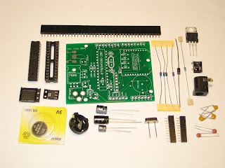
This project is actually a revisit of my old Wiseduino , with the same goal: an Arduino-compatible with on-board Real Time Clock, and some extras (in this case, an XBee-like device, e.g. BTBee, GPSBee, WiFly). I renamed it " wsduino ", although the pronunciation should remain the same :) I redesigned  wsduino  mainly for the Axiris IV3 clock , whose enclosure allows for only 2 boards (Arduino + IV3 shield), with openings for power socket, USB, and no accessible buttons. Essentially, wsduino saves you an extra shield, which would have hosted the RTC (+backup battery) and the XBee.  US$27 - free shipping to North America wsduino is now available as a kit, as shown in the photo below. The wsduino kit includes: PCB ATmega328 processor with bootloader 28-pin socket 16MHz crystal 2 x 22pF capacitor power jack 7805 voltage regulator 1N4001 diode USB miniB socket DS3231 RTC (SMD) A1117 3V3 regulator (SMD) CR1220 battery + holder 4 x 10k resistor 4k7 resistor 3 x...

WiFiChron clock kit now available

Image
Update Sep 18, 2017:   Here is the latest revision of the PCB included in the kit. Update Oct 8, 2015 : The latest revision of the PCB (pictured here and here ) has hardware support for XBee (which also covers GPSBee, WiFiBee and BTBee). With this kit you build a clock like the ones shown in the photos below. Last one, courtesy of Nick, features an yellow/amber display. There are two buying options: 1. use or make your own enclosure  (US$47, free shipping to North America) 2. enclosure included ( Serpac A20 , transparent front panel, screws, back panel hand-drilled with 3 holes for buttons and rectangular opening for the USB connector )  (US$61, free shipping to North America) The kit includes the following electronic parts: main PCB display adapter PCB ATmega328 with 8MHz bootloader, programmed with a clock sketch + 28-pin socket 74HC595 shift register + 16-pin socket HDSP-2534 8-character alphanumeric display + 4 x 6-pin machined headers DS3231 + ...

ProMini clock shield with OLED display

Image
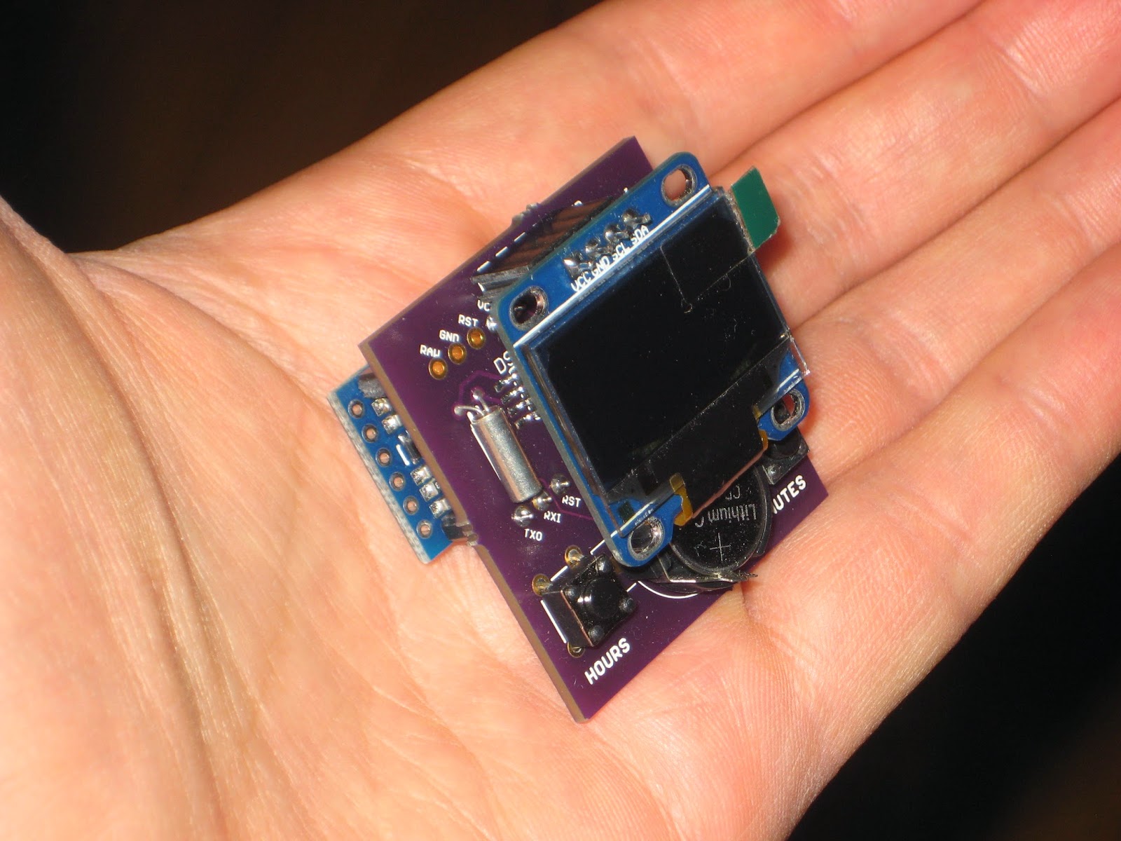
Yet  another ProMini clock shield kit, this time featuring a 128x64 I2C OLED display. The kit can be purchased with or without the OLED display (I prefer you buy the OLED on your own, for example this excellent one from miker ).   US$30, includes OLED display, free shipping to North America   US$16, OLED not included, free shipping to North America The kit includes: PCB DS1307 SMD 32kHz crystal CR1220 coin battery battery holder optional: I2C 128x64 OLED display (blue or white) tactile switch (2x) resistor 10k (2x) machined male pins The PCB was designed to accommodate I2C OLED displays with the 4-pin header configured either as VCC-GND-SDA-SCL or as VCC-GND-SCL-SDA. The OLED clock can also be powered from the same LiPo battery shield for ProMini, as used in the bubble clock. To minimize current consumption (beside disabling the ProMini on-board LEDs), the processor can be awaken from sleep at the push of the "hours" button (on D3). Schematic and board layout ...

ProMini clock shield with 7-segment bubble display

Image
Update May 6, 2016: This kit is no longer offered until I get a new batch of QDSP-6064 displays (whose price seem to have jumped considerably). This clock was designed as a ProMini shield. It comes as a mostly-SMD kit, based on DS1307 with battery backup and the QDSP-6064 7-segment LED "bubble" display. The kit includes the following: PCB QDSP-6064 DS1307 SMD 32kHz crystal CR1220 coin battery battery holder 330 ohm resistor 0805 (8x) tactile switch SMD (2x) machined female pins The assembled clock can be fitted with a LiPo battery shield for ProMini, as shown in this post  (source code also provided there). The current draw (measured at 20mA with an unmodified ProMini) can be minimized by removing the 2 LEDs on the ProMini board, as well as dimming the 7-segment bubble display through software (SevSeg library). One other way of maximizing the LiPo battery life cycle is by waking the clock from sleep mode at the press of the "minutes" button (on D2). Schematic and ...

New kit in store: simple clock with HDSP-2534 display

Image
The centerpiece of this clock kit is the vintage-style 8-character display HDSP-2534 originally from HP, currently manufactured by Avago. The assembled clock looks like in the photo below. The dock, not included in the kit, is a miniB USB phone charger; it can be easily sourced from ebay , if you don't already have one. (You can even get a fancy one, e.g. custom-made exotic wood, on etsy.com .) The kit includes the following components: PCB; ATmega328P, with bootloader and fuses for 8MHz internal clock, and the sketch preloaded (also downloadable from here ); HDSP-2534 display ; 595 shift register; DS1307 real time clock; 32kHz crystal CR1220 battery; battery holder; push buttons (x2); capacitor 100nF (x3); 10k resistor (x3); 28-pin socket; 16-pin socket; 8-pin socket; 6-pin machined female header (x4).    $40, free shipping to North America Note: The kit is currently out of stock. Please send me an email (my address is in the top right corner of the page) if you want one. I ...

Black Friday (and beyond) sale

Image
I was going to have a Black Friday sale anyway, but now I have one more reason for it, and it's an embarrassing one: the latest batch of PCBs have a little flaw, but they can be easily fixed. So, until I run out of them, both the Wise Clock 4 kit and the Complete Wise Clock 4 kit  will be $10 less, for $57 and $115 respectively. (As always, I also offer discounts for multiple units, just ask.) The photos below show a few ways to fix it. Basically, the GND terminal of the USB connector is disconnected from the board's ground. The short wire re-connects them again. The sleekest way would be on the bottom, using a resistor terminal inserted together with the 2x8-pin female header, as shown in the photo below. Solder the other end together with the 6-pin FTDI connector. Here is the story of how this happened. The PCB used to be 101.2 mm in length. That was 1.2 mm longer than the 10 cm limit imposed when using Seeedstudio's PCB prototyping service. I never had a problem before,...

Buy Complete Wise Clock 4 kit - includes display and enclosure

Image
Update July 7, 2015 Before you buy, please read this post on assembling the Wise Clock 4 with the new display. When you buy the " Complete Wise Clock 4 kit ", on top of the Wise Clock 4 kit  you get the 3216 bi-color (red/green/orange) LED display from Sure Electronics, plus the enclosure, consisting of two laser-cut transparent acrylic plates and the required hardware (standoffs, screws etc) to assemble it.   US$125  US$115 - free shipping to North America The " complete kit " comes with everything you need to build a functional Wise Clock 4 . You will need to add your own FAT16/FAT32-formatted SD card (with the necessary files on it), the miniB USB power cable and, eventually, an BTBee module (if you want Wise Clock 4 to display messages sent from your Android device). The assembly guide, written by StefanK, can be found here .

Buy Wise Clock 4 kit

Image
The Wise Clock 4 kit includes the following parts (shown in the photo below): PCB; SD card socket (pre-soldered); DS3231 extremely accurate RTC (real time clock) chip, soldered to the board; MIC5219 voltage regulator, soldered to the board; 74HC125 level shifter (5V to 3V3), soldered to the board; 2 SMD LEDs (soldered); 3 SMD resistors (soldered); ATmega644P, with the latest Wise Clock 4 software; 40-pin socket;  16MHz crystal; 2 x 22pF ceramic capacitors; CR1220 backup battery for RTC; holder for the coin battery; 3 x right-angle push buttons; 9 x 10k resistors; 3 x 4k7 resistors; piezo buzzer; USB miniB connector; 6-pin right-angle male header (FTDI connector); two 2x8-pin female headers (display connectors); two 10-pin 2mm female headers (XBee connectors); 220/470 uF electrolytic capacitor; 3 x 100nF decoupling capacitors. Note that the first bunch of components in the list are SMDs and come soldered to the board (that is, I solder them for you). US$67  US$57,...

Freebees

Image
Purchase any of my kits and you can get one  (or more, if you ask nicely :) freebee from this page (just email me with your choice). I am currently giving away a few "surplus" boards and LED matrices. Shown below are, from left to right: PCB for the LED matrix shield ; PCB for Wiseduino rev. 1.7 ; PCB for the Dual bi-color LED matrix shield rev 1.4 ; PCB for the Dual bi-color LED matrix shield rev 2.0 ; You can also get the PCB for DWex , a small Arduino + RTC, that you can make into a DIY pocket/pendant watch. This board is mostly SMD, but not difficult to solder with a little exercise. Any of the above PCBs can be used as originally intended (for kits), since there is nothing wrong with them (as far as I know). The challenge in building the LED matrix shields is in finding the right matrices (which is almost impossible, since they were "kind-of" custom made for me by a Chinese LED company some time ago). Nevertheless, one can connect other (compatible, that is co...