Posts

Showing posts with the label I2C

Experimenting with MAX6955

Image
MAX6955  is an interesting LED driver chip. It is the primordial charlieplexing device, being the materialization of a technique invented by Charlie Allen of Maxim Integrated. Without understanding how charelieplexing works, it is actually counter-intuitive to wire multiple (up to 8) 16-segment displays to such a driver chip. Fortunately, Maxim has great documentation on how to do it. My experimenting actually started with MAX6954 . After many failed tries due to SPI issues (Maxim uses a special interpretation of the protocol, I read), I switched to MAX6955. MAX6955 is the I2C sibling of MAX6954 (which uses SPI). They both have identical LED driving abilities, only the microcontroller interface part of the chips differ. Once, both chips were available in DIP-40 package. Now, MAX6955 only comes in SSOP-36 (MAX6954 is still available in DIP-40). Luckily, the pin configurations for the two chips are compatible, which allows for easy swap. For this reason, I designed a breakout board...
OLED clock with Pacman mode

Image
This large 2.42" OLED I2C module can be used as a replacement for the smaller 0.96" display for which I originally designed the ProMini OLED clock shield . It is built around the same SSD1306 chip, and it only comes in yellow (for now). MikeM wrote this great Pacman clock sketch for it (available for download here ), shown in the video below. To display on the OLED, Mike used U8glib graphic library. Initially tested on the 0.96" OLED, the sketch froze after some time, for a yet to be explained reason. The same sketch works perfectly with the 2.42" display. Mike spent a lot of time trying to figure out if the culprit is software (bug in the U8glib) or hardware. (Any feedback on this issue is greatly appreciated.) The clock can also display the time as HH:MM:SS on the whole screen, as shown in the photo below, also courtesy of Mike. My next step would be to design an enclosure for it. For that I will probably need some more help :) Update Nov 29, 2014, from MikeM: ...

ProMini clock shield with OLED display

Image
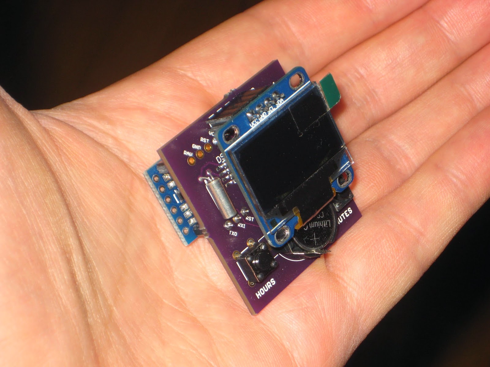
Yet  another ProMini clock shield kit, this time featuring a 128x64 I2C OLED display. The kit can be purchased with or without the OLED display (I prefer you buy the OLED on your own, for example this excellent one from miker ).   US$30, includes OLED display, free shipping to North America   US$16, OLED not included, free shipping to North America The kit includes: PCB DS1307 SMD 32kHz crystal CR1220 coin battery battery holder optional: I2C 128x64 OLED display (blue or white) tactile switch (2x) resistor 10k (2x) machined male pins The PCB was designed to accommodate I2C OLED displays with the 4-pin header configured either as VCC-GND-SDA-SCL or as VCC-GND-SCL-SDA. The OLED clock can also be powered from the same LiPo battery shield for ProMini, as used in the bubble clock. To minimize current consumption (beside disabling the ProMini on-board LEDs), the processor can be awaken from sleep at the push of the "hours" button (on D3). Schematic and board layout ...

ProMini clock shield with 7-segment bubble display

Image
Update May 6, 2016: This kit is no longer offered until I get a new batch of QDSP-6064 displays (whose price seem to have jumped considerably). This clock was designed as a ProMini shield. It comes as a mostly-SMD kit, based on DS1307 with battery backup and the QDSP-6064 7-segment LED "bubble" display. The kit includes the following: PCB QDSP-6064 DS1307 SMD 32kHz crystal CR1220 coin battery battery holder 330 ohm resistor 0805 (8x) tactile switch SMD (2x) machined female pins The assembled clock can be fitted with a LiPo battery shield for ProMini, as shown in this post  (source code also provided there). The current draw (measured at 20mA with an unmodified ProMini) can be minimized by removing the 2 LEDs on the ProMini board, as well as dimming the 7-segment bubble display through software (SevSeg library). One other way of maximizing the LiPo battery life cycle is by waking the clock from sleep mode at the press of the "minutes" button (on D2). Schematic and ...

Arduino I2C Tutorials

Image
I2C Communication: This Arduino tutorial covers using I2C to communicate with an EEPROM chip. Arduino to Arduino I2C: Using I2C to communicate between two Arduinos.

Arduino Wire Library for I2C communication

Image
The Wire Library allows developer to communicate with I2C / TWI devices. On the Arduino boards with the R3 layout (1.0 pinout), the SDA (data line) and SCL (clock line) are on the pin headers close to the AREF pin. The Arduino Due has two I2C / TWI interfaces SDA1 and SCL1 are near to the AREF pin and the additional one is on pins 20 and 21. remark: TWI stands for Two Wire Interface and for most marts this bus is identical to I²C. The name TWI was introduced by Atmel and other companies to avoid conflicts with trademark issues related to I²C.

I2SDv3 - Arduino buckler with microSD

Image
The Wyolum machine  ( these are the people who generously offered $3000 in innovation grants , with no strings attached ) is forging ahead with a new and improved version of I2SD . I just received their v3 prototype and it looks impressive. I must say it is the most feature-rich data logger / SD card backpack (here is the list of the competing products that I compared with). Like its predecessor, I2SD v3 is a software-compatible Arduino (ATmega328/16MHz) with extras. It has on-board microSD card, DS3231  extremely accurate real-time-clock with backup battery, infrared receiver and 2 LED indicators for errors or status. I2SDv3 comes assembled (all SMD), with the bootloader burnt in. Sketches can be uploaded through the FTDI connector. The board can be plugged directly into Arduino, using one row of headers (A0-A4-GND-RST), hence the name " buckler " (like a "semi-shield", got it?) I2SDv3 also offers header access to D4-D7 (v2 lacked that; my complaint wa...

I2SD kit

Image
A while ago I received the good-looking  I2SD kit  from Wyolum . This is another open source project created and generously shared by the same team that brought us ClockTHREE and C3Jr . The I2SD kit is pictured below. As you can see, it is mostly SMD (0805 and SOIC packages). Not for a novice, but definitely easy to solder by anyone with a steady hand and a good pair of eyes. As always, when I assemble a kit, I try to skip the "read the manual" part. I don't recommend this to anyone though. This is just a test for me to assess how user-friendly the kit is. (Note: Ironically, this test would fail for my own  Wise Clock 3 kit because of the 3 resistors of 4K7. One really need to know exactly where those resistors go (R5, R6 and R7). An improvement in a future version of Wise Clock 3 would be to have the resistor values on the silkscreen, as C3Jr has.) Well, the I2SD kit passed the "no manual required" test, which means that the kit is well thought and desi...