Posts

Showing posts from February, 2015

WiFiChron clock kit now available

Image
Update Sep 18, 2017:   Here is the latest revision of the PCB included in the kit. Update Oct 8, 2015 : The latest revision of the PCB (pictured here and here ) has hardware support for XBee (which also covers GPSBee, WiFiBee and BTBee). With this kit you build a clock like the ones shown in the photos below. Last one, courtesy of Nick, features an yellow/amber display. There are two buying options: 1. use or make your own enclosure  (US$47, free shipping to North America) 2. enclosure included ( Serpac A20 , transparent front panel, screws, back panel hand-drilled with 3 holes for buttons and rectangular opening for the USB connector )  (US$61, free shipping to North America) The kit includes the following electronic parts: main PCB display adapter PCB ATmega328 with 8MHz bootloader, programmed with a clock sketch + 28-pin socket 74HC595 shift register + 16-pin socket HDSP-2534 8-character alphanumeric display + 4 x 6-pin machined headers DS3231 + battery holder + CR1220 coin batte

How To Make a PC Control Robot

Image
Do you ever tried to control your robot using your PC or laptop? Controlling a robot using PC or laptop is often being a fun for the student or hobbyist. Thus during this article you will be tend to learn how to control your robot using your PC or laptop. Here it is assumed that you know  How To Send Serial Data From Arduino To Laptop or PC  and  How To Receive and Send Serial Data Using Arduino Board . Thus lets begin to making this awesome DIY hack today with us. Replica of robot Component Required: Arduino UNO Board PC/Laptop L293D Motor Driver IC 2 Motor Serial Bluetooth Module 2 wheels Chassis Castor wheel Software (serial port software on your PC/laptop)  Click here to see more projects on Arduino Block Diagram: Block Diagram Setup Connection For Robot: Circuit Diagram Here we use a L293D motor driver IC which is used for the controlling the rotation of the two motor connected to robot. Pin no 2,7,10,15 of L293D motor driver IC is connected to the pin no 9,8,7,6 of arduino board.

Controlling LEDs With PC Using Arduino

Image
Wireless communication plays a very important role within the communication system. We may be able to send data from one point to another point simply through wireless communication. There is such a large option available for the wireless communication like Bluetooth, Wi-Fi etc. In this article, we concern only in Bluetooth. Bluetooth is a standard wireless technology which transfers the information over very short distances. It is assumed that you just ought to knowledge to  How To Send Serial Data From Arduino To Laptop or PC  and  How To Receive and Send Serial Data Using Arduino Board After Reading this article you will be able to control LED via your PC/Laptop. For controlling the led we use arduino board  Introduction to Arduino Board .  Circuit diagram: Here we use three led blue, green and red that are connected to pin no. 10,9 and 8 of arduino board respectively. We also connect an LCD display module to arduino board. read this post for  Interfacing LCD With Arduino UNO . Al

How To Receive and Send Serial Data Using Arduino Board

Image
Serial communication is the easiest way to communicate with the peripheral device in embedded system. Thus, during this article, you may be able to learn the way to receive and send serial data from the arduino board. If you are beginner then first read this Introduction to Arduino Board  and How To Send Serial Data From Arduino To Laptop or PC  before moving on this article. Arduino ide has such a big amount of inbuilt function for serial communication and detail of some function are here   How To Send Serial Data From Arduino To Laptop or PC . During this article, we tend to use some additional function that facilitates us to receive the serial data from the serial port. These functions are Serial.available(), Serial.read(), Serial.write whose explanation are given below: 1: Serial.available() This function is always used before the Serial.read() function. This function returns always a positive value once reception is complete. This function is used for whether or not entire data is

How To Send Serial Data From Arduino To Laptop or PC

Image
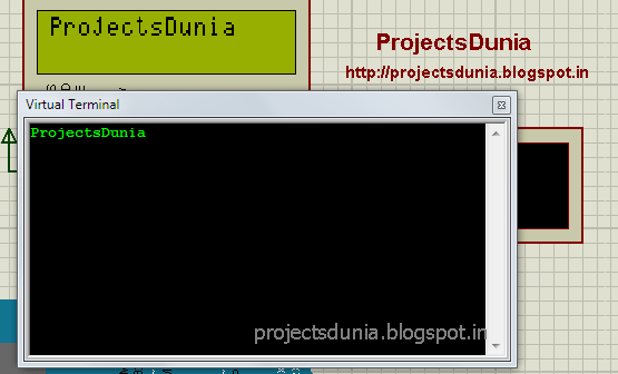
Serial Communication plays important role within the communication system. All micro-controller should have serial communication port.Serial communication provides a text-user-interface(TUI). One will use serial port of microcontroller to send data serially to laptop/PC or receive data serially from laptop/PC.Here we use arduino board to communicate with the laptop. Arduino board have a minimum of one serial port to communicate known as UART and USART. It communicates with digital pin 0 and 1 of arduino refer to as RX and TX pin as well as with the computer via USB. Virtual Terminal Interfacing LCD With Arduino UNO Arduino has a built-in function for serial port thus there is no need to go into register detail. In Arduino IDE, one can easily call the serial function for the serial port and job is finished. A simple connection for serial communication is shown below Connection For Serial Communication For serial communication with arduino, we have to use three function known as Serial.b

How To Interface Seven Segment Display With Arduino

Image
A seven segment display is an electronic display device for displaying numeral. Seven segment display are widely used in the digital clock, TV, electronic meter and other electronic devices which display numerical value. Simple seven segment display image is shown below: Seven-segment Display may be used in two modes: 1: Common anode ( all of the positive terminal are connected)  2: Common cathode (all of the negative terminal are connected) In this tutorial, we tend to use common cathode mode to display the numerical number. Interfacing LCD With Arduino UNO Circuit diagram Arduino pin 2,3,4,5,6,7,8,9 is directly connected to a,b,c,d,e,f,g,h data pin of seven segment display as shown in image: Circuit Diagram Program Code for one digit count down timer from nine to zero is written in arduino ide as shown in image. Code Copy or download the code and paste it within the empty sketch of arduino ide and so compile the sketch and upload it to your board. Now enjoy count down timer using sev