Posts

Showing posts from July, 2015

How to Interface 4*3 Keypad With Arduino

Image
In this article, we will find out how to interface a matrix keypad with arduino in very easy technique. During this article, we are using a 4*3 matrix keypad. Keypads are a very important component in the embedded system which are used in various mini or major comes and the commercial product like telephone, electronic locker, and alternative automation product. At the end of the article you may be ready to interface a matrix keypad together with your arduino and after you press a key, its shows up into the serial monitor. What is 4*3 Matrix Keypad One of the most frequently asked question among the students or hobbyist are when we use 4*3 or 4*4 matrix keypad and what is the difference between them. Therefore, we have only one answer what's your requirement within the project. The logic behind operating of each keypad are same. The 4*3 keypad is simple keypad having 4 rows and 3 column, therefore, total 12 keys as shown in the image. There are so many distributors wherever you wi...

Experimenting with MAX6955

Image
MAX6955  is an interesting LED driver chip. It is the primordial charlieplexing device, being the materialization of a technique invented by Charlie Allen of Maxim Integrated. Without understanding how charelieplexing works, it is actually counter-intuitive to wire multiple (up to 8) 16-segment displays to such a driver chip. Fortunately, Maxim has great documentation on how to do it. My experimenting actually started with MAX6954 . After many failed tries due to SPI issues (Maxim uses a special interpretation of the protocol, I read), I switched to MAX6955. MAX6955 is the I2C sibling of MAX6954 (which uses SPI). They both have identical LED driving abilities, only the microcontroller interface part of the chips differ. Once, both chips were available in DIP-40 package. Now, MAX6955 only comes in SSOP-36 (MAX6954 is still available in DIP-40). Luckily, the pin configurations for the two chips are compatible, which allows for easy swap. For this reason, I designed a breakout board...

LED driver chips

Image
After looking at the many options for driving LED displays (5x7/8x8 matrix, 7/14/16/25 segment, common anode/cathode, single/bi-color/RGB), I put together this list of commonly used LED driver chips, to have a better picture of possible combinations, and use it as reference for future projects. The bottom 5 rows are not actually LED drivers, just substitutes (require current limiting resistors). Some of the driver chips (e.g. "8x8" in the "channels" column) provide internal multiplexing, being designed specifically for driving array of LEDs. The others, where "channels" is just one number, would require extra circuitry (e.g. transistors) and logic (micro controller code) for multiplexing. The "CA" column indicates "common anode", "CC" stands for common cathode. There seem to be more options for driving common anode LED displays, probably because sinking current (by the chips' LED outputs) allows for higher currents and als...

Wise Clock 4 with the new 3mm 3216 LED display from Sure

Image
My inventory of "old" 3216 3mm displays from Sure Electronics is now depleted. As everybody already knows by now, Sure redesigned the display to be powered with 12V instead of 5V (plus a few other cosmetic changes). The Wise Clock 4 board cannot be plugged into the new display's connectors anymore, since they are now different (10 pins instead of 16), and the assignment of signals to pins has changed as well. Making a seamless  Wise Clock 4 with the new display is still possible, with a little more soldering work. The board will be connected to the display using the ribbon cable provided. To do this, cut one connector off the ribbon cable, then solder 5 wires (4 signal + ground) from the cut end of the ribbon, in the place of the header, as shown in the photo below. The 5V power line from the clock's board (red wire in the photo) will be soldered separately from the ribbon cable, bypassing the display's 5V regulator, as shown in the next photo. The new display ...

My impression of Akafugu Nixie Modular Clock

Image
You are reading the first ever "review" of the Akafugu Nixie Modular Clock , a product yet to be released at the time of writing. Per, of Akafugu, generously offered to sell me the PCBs for this Nixie clock; the parts were sourced by myself. The Nixie Modular Clock shares a big chunk of the schematic with its older sibling, the Akafugu Nixie Clock . The goal of this latest design is, I assume from the name, the "modularity". Similar to the VFD Modular Clock , "shields" for various types and numbers of Nixie tubes will probably be developed soon. The hardware This Nixie Modular Clock is an Arduino-based, open source project, designed around ATmega328 running on internal oscillator at 8MHz. Like the Akafugu Nixie mk3, the high voltage source (180-200V) uses the MC34063 DC-DC converter, and the driver for Nixies is HV5812 . There are 3 buttons: 2 in the back, for setting up the time and alarm time, and another long-stem, protruding through the top board, for...

Introducing wsduino

Image
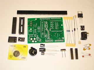
This project is actually a revisit of my old Wiseduino , with the same goal: an Arduino-compatible with on-board Real Time Clock, and some extras (in this case, an XBee-like device, e.g. BTBee, GPSBee, WiFly). I renamed it " wsduino ", although the pronunciation should remain the same :) I redesigned  wsduino  mainly for the Axiris IV3 clock , whose enclosure allows for only 2 boards (Arduino + IV3 shield), with openings for power socket, USB, and no accessible buttons. Essentially, wsduino saves you an extra shield, which would have hosted the RTC (+backup battery) and the XBee.  US$27 - free shipping to North America wsduino is now available as a kit, as shown in the photo below. The wsduino kit includes: PCB ATmega328 processor with bootloader 28-pin socket 16MHz crystal 2 x 22pF capacitor power jack 7805 voltage regulator 1N4001 diode USB miniB socket DS3231 RTC (SMD) A1117 3V3 regulator (SMD) CR1220 battery + holder 4 x 10k resistor 4k7 resistor 3 x...

Wiseduino Next Generation

Image
You have a "tube shield" like the Axiris IV3 shield or the Nixie shield and you want to make a clock. You will definitely need an Arduino. You can either program it to (roughly) count the seconds, minutes, hours, or you can add an extra RTC, specialized in (accurate) time keeping, and program your Arduino to just get the time from RTC. The latter is Wiseduino , the first board I ever designed (also discontinued a long time ago). I badly needed one to finish the Axiris IV3 clock, since neither the software solution (second-counting) nor the hardware solution (adding a second RTC shield) was suitable. And so I re-designed it, improved on existing features (power, RTC) and added new ones (support for XBee/BTBee/GPSBee). This new version, spelled " wsduino " (but still pronounced " wiseduino ") is shown below, next to the Axiris IV3 shield. The wsduino board has an Arduino-compatible footprint, so it fits perfectly in the Axiris-designed-and-made enclosure ...